26 aprile 2017

Come sostituire la batteria al mitico Kenwood R-5000

Come sostituire la batteria al Kenwood R-5000
By Giovanni Carboni IZ5PQT


Prima di tutto occorre rimuovere i coperchi inferiore (9 viti) e superiore (8 viti) e sconnettere l'altoparlante interno


A me la batteria originale è durata 20 anni. Vedremo questa! 73

25 aprile 2017

Come ti rimetto in funzione il Lowe SRX-30


SCHEDA DI MANUTENZIONE DEL LOWE SRX-30
di Michele D'Amico IZ2EAS


Sabato 01 aprile 2017

La radio si accende ma non riceve nulla, solo il soffio in BF. Il problema è il divisore x10 TTL 7490PC, guasto; sono infatti scomparse le “righe” ogni MHz e sono presenti solo multipli di 10 MHz (il master clock). Questo guasto è tipico, è la seconda radio (su due che ho riparato) di questa famiglia che presenta questo problema. Sostituito con il più moderno 74LS90, montato su zoccolo. La radio ora funziona perfettamente. Riallineato l’oscillatore a cristallo da 10 MHz.


Domenica 02 aprile 2017

Riallineato il VFO e la IF “tracking” 2-3 MHz, seguendo il service manual del Drake SSR1, molto preciso e dettagliato (le due radio sono praticamente identiche).

Riallineata la IF a 455 kHz, iniettando il segnale del generatore R&S sulla base di Q9 (come da service manual del SSR-1). La risposta è asimmetrica in AM ma abbastanza simmetrica in LSB/USB.

Ho ritarato leggermente il BFO: frequenza USB 454.1 kHz, frequenza LSB 457.2 kHz, corrispondente ad uno shift tra i due modi di circa 3 kHz.

Rimosso un circuito “estraneo” nella linea di alimentazione a 12 V esterni, uno stabilizzatore di tensione a transistor che un “sarchiaponatore” misterioso aveva introdotto. Sostituito con un semplice diodo di “non ritorno”, 1N4002 (100V, 1A).

Lubrificati tutti i meccanismi rotanti. Disossidati i commutatori. Pulizia generale e derattizzazione.
(Fusibile installato: 1 A Fast grande, corretto)


Al termine del lavoro la radio suona come un violino !


07 aprile 2017

Modifica allo Yaesu FRG-7000: filtro stretto anche in AM


Yaesu FRG-7000: a modification to use the narrow filter in AM mode
(by Michele D’Amico IZ2EAS)

Introduction

The Yaesu FRG 7000 is a colorful, vintage receiver that is still fun to use. The main drawback when used in AM mode is the availability of only one IF bandwidth, that is way too wide (9kHz at –6dB, measured) in crowded band conditions (What ? “Crowded bands” in 2017 ?). The narrow filter (2.8 kHz at – 6dB) is accessible only in USB/LSB modes.

However, this limitation can be overcome with a very simple modification, that is absolutely not-invasive and completely reversible. With this modification when you select the AM mode the receiver uses the Wide Filter, while when you select the AM-ANL mode the receiver uses the Narrow Filter.

But first let me state it very clearly: do it at your own risk. I will accept no liability for any damage you will do to your radio, to yourself or to this sector of the Universe by following the procedure outlined in this document.

Please feel free to contact me if you want to exchange ideas at: iz2eas(AT)gmail.com

The mod

Since the filters are selected electronically by activating a diode, the modification is very simple: just “cut” a connection on the “mode” switch and rewire it. This will allow you to select the Narrow Filter in AM-ANL mode, while the standard AM mode uses the Wide Filter.

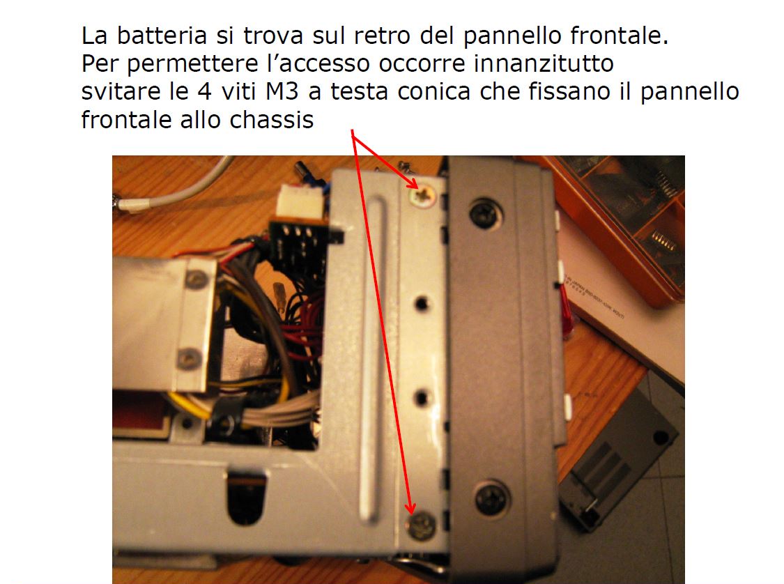
The mode switch is easily accessible from underneath the radio, there is no need to dismount anything apart removing the receiver’s cover; the photo below shows the position of the mode switch (circled in red).


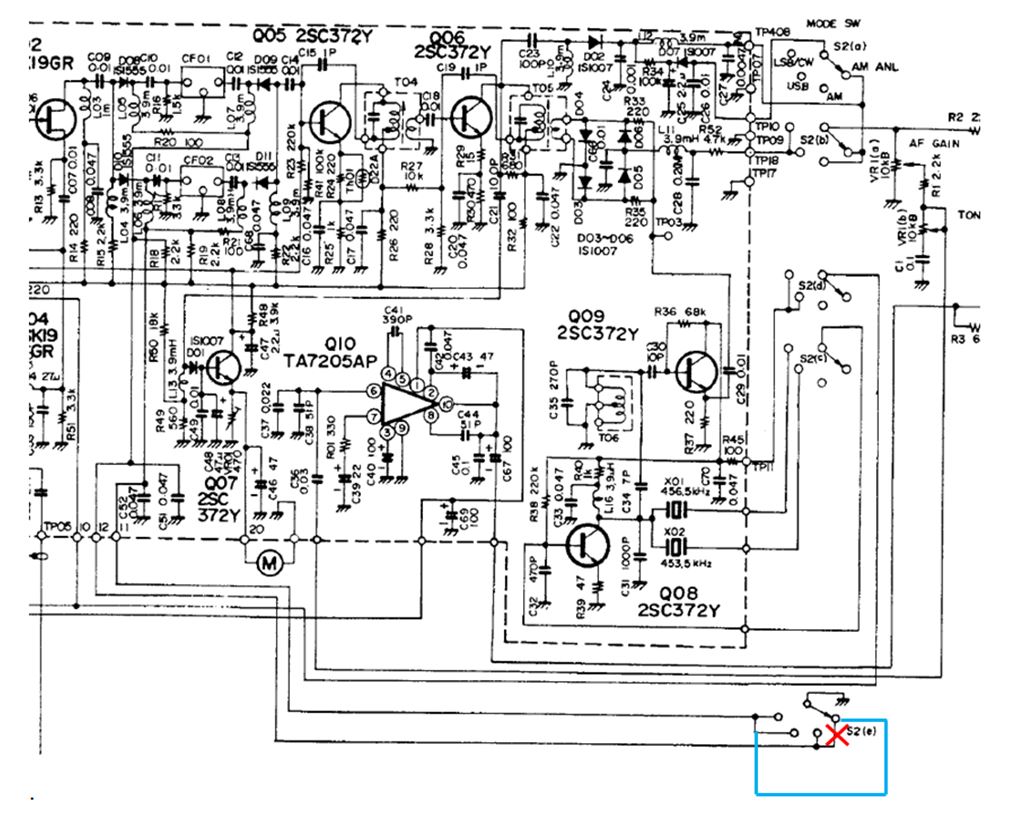
In the schematic below the modification is shown: just “cut” a connection (red cross) on S2(e) switch and rewire it with the blue wire. The section (e) of switch S2 select the desired IF filter (CF01 –wide- or CF02 –narrow-) by grounding a diode (and hence activating it). 

As standard, CF01 is selected for AM and AM-ANL modes, and CF02 for USB and LSB modes. By rewiring section (e), we activate CF01 only for AM, and CF02 for USB/LSB/AM-ANL; as simple as that !

Please note that I kept the ANL circuit operative, since I could hardly notice its effect; if you want, you can disable it but then the modification will be more invasive and you will need to rewire also section (a) of S2.

On the left the band switch before the mod. The connection that need to be interrupted is the one circled in blue, easily accessible, where the white-and-blue wire is connected.
There is no need to dismount the switch.

The two pins of the switch are soldered together; I cut the wire and then used a de-soldering pump to remove the solder and separate them. See:


On the right the band switch after the mod. Note the added green wire that jumpers the fourth (and last) pin of the switch (AM-ANL position) to the first and second pins (USB/LSB position), i.e. to the white-and-brown wire.

The white-and-blue wire is now connected only to the third pin (AM position). See:

03 aprile 2017

Nuovo ricevitore SDR Airspy HF+: informazioni ufficiali


Non molto tempo fa avevo annunciato l'arrivo del nuovo ricevitore SDR Airspy HF+ (Clicca qui per leggere). Adesso è comparsa anche una pagina sul sito del produttore, pagina che però non riporta alcuna immagine.

Si spiega però la filosofia costruttiva del nuovo ricevitore con tutta una serie di informazioni utili per gli appassionati. Vi consiglio di dare un occhio a questa pagina: CLICCA QUI

Le specifiche tecniche fornite appaiono molto interessanti:

HF coverage between DC .. 31 MHz
VHF coverage between 60 .. 260 MHz
-138 dBm MDS at 500Hz bandwidth in HF
-142 dBm MDS at 500Hz bandwidth in VHF
+26 dBm IIP3 on HF at maximum gain
+13 dBm IIP3 on VHF at maximum gain
110 dB dynamic range in HF
95 dB dynamic range in VHF
120 dB Image Rejection
Very low phase noise PLL (-110 dBc/Hz @ 1kHz separation @ 100 MHz)
+10 dBm Maximum RF input
No Silicon RF switch to introduce IMD in the HF path
Routable RF inputs
Wide Band RF filter bank
Tracking RF filters
Sharp IF filters
Smart AGC with real time optimization of the gain distribution
All RF inputs are matched to 50 ohms
2 x High Dynamic Range Sigma Delta ADCs @ up to 36 MSPS
600 kHz alias and image free output
18 bit Digital Down Converter (DDC)
0.5 ppm high precision, low phase noise clock
4 x Programmable GPIO’s
No drivers required! 100% Plug-and-play on Windows Vista, Seven, 8, 8.1 and 10
Industrial Operating Temperature: -45°C to 85°C